TL’DNR: My steps towards emulating an Amiga 1000 keyboard, using the GPIO (input/output) pins of a Raspberry Pi, and implementing parts of the keyboard protocol in Python.
Background
Around 1997 I got an Amiga 1000 (“A1000”), without keyboard or
floppies. Released in 1985, the A1000 has no harddisk, and after
booting is asking for a 3.5" floppy disk with kickstart firmware.
Once that is loaded, another floppy with the workbench (a graphical
interface) or floppies with applications or software could be inserted.
The disk drive is different from PC 3.5" drives, to obtain these floppy
disks I
- connected an Amiga 500 via serial cable to a Linux box
- inserted an unused floppy
- and had the A500 floppy write the images of kickstart and workbench
Details are on the wiki.
With these floppy disks, the A1000 booted fine into the workbench.
Also games like Turrican 2 did start up, and worked with a joystick.
The mouse also worked. Just no keyboard..
Hardware
The A1000 has a 4 port connector for the keyboard, which turned out to be rj10/rj22. As of 2025, in Germany, cables with fitting connectors are sold as “handset cord” (“Hoerer Kabel”), so the cable connecting the handle with microphone/speaker to a classic telephone. At my first attempt, I got rj11 plugs delivered - these are to wide and to not fit the A1000 keyboard outlet.
So, the idea to implement the protocol which the A1000 is expecting from the keyboard, and transmit keystrokes. How hard could it be?
This is the required hardware:
- rj10/rj22 plug with cable, used to interface with the A1000
- Raspberry Pi or a similiar device which can set single output pins. The GPIO from the Raspi is nicely supported, and the Raspi also runs fully fledged Linux, which I’m more comfortable with than first having to adapt to a development kit of smaller hardware.
- 5v/3.3V logic level shifter, as the Raspi is working with 3.3V on its GPIOs, while the Amiga is working with 5V
- Multimeter to measure voltage is convenient
- An LED, a 330Ω resistor to confirm power direction
- solder iron
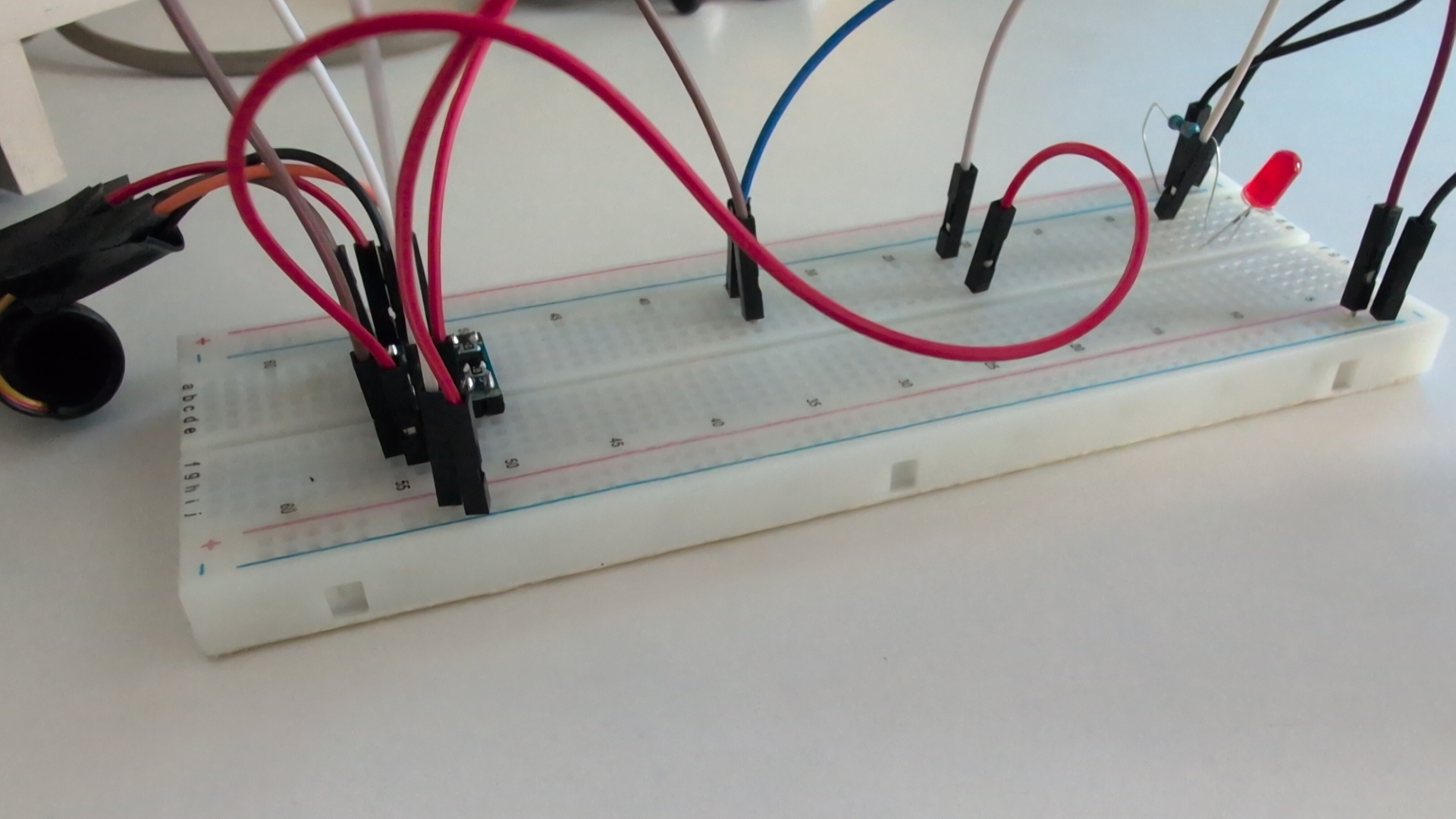
- breadboard, a piece of plastic with holes which are connected in a defined pattern. When we stick pins with wires into the holes, the board is creating electrical connections. All of this could also be done with soldering, but the breadboard is much better for quick prototyping connections.
- some cables with pins, these are for use with the bread- board
Sets of breadboards with cables, LEDs and resistors can be ordered from many places.
Raspi setup
I did choose the Raspi to be sure to have enough computing power, and to have a full Linux available. After flashing Raspberry Pi OS, I looked up simple guides and got simple Python code together to confirm these:
- LED blinking, to verify GPIO is working
- GPIO input: so when then shorting out 2 contacts on the breadboard with a cable, the Python code would notice and report this
Hardware setup, Amiga side
Starting with the Amiga side, I bought a cable with rj10/rj22 connectors on both ends, cut it into half, separated the 4 single cables inside, and soldered them to 4 short cables with pins at the end. These 4 pins can then be plugged into the breadboard for further experiments.
Details on the pin layout are here, we will refer to these as
- pin 1: +5V
- pin 2: CLOCK
- pin 3: DATA
- pin 4: GND
With the multimeter, at this point we can verify:
- that there is 5V current between +5V and GND
- also 5V between CLOCK/GND and between DATA/GND
Bringing the hardware together
Next, I soldered pin-rows to the level-shifter board and placed it on the breadboard. We need the level-shifter to translate between the 5V signals from the Amiga, and the 3.3V signals from the Raspi. If your hardware can directly deal with 5V (i.e. most Arduino do), then you do not need the level-shifter.
To operate properly, the level-shifter needs 5V supplied on HV/GND, the Amiga is providing that for us. The level-shifter also needs 3.3V on LV/GND, we take that from the Raspi.
This order should then be used for connecting:
- The 4 pins from the Amiga should be connected to the level-shifter. Amiga-GND goes to Shifter-GND, Amiga-+5V goes to Shifter-HV, Amiga-CLOCk goes to HV2, Amiga-DATA goes to HV1.
- We then connect 3.3V to LV and the GND next to that to the Raspi
- With that, we can use the multimeter and should confirm that we see 3.3V between LV1/GND(on LV-side) and LV2/GND(on LV-side).
The Amiga is setting these 2 lines “up” for us, and with the Raspi we will set these “down” for the signals.
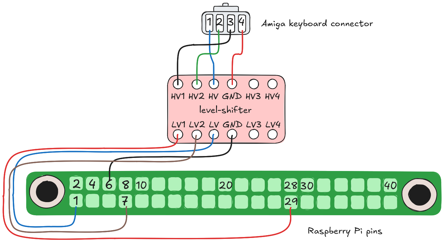
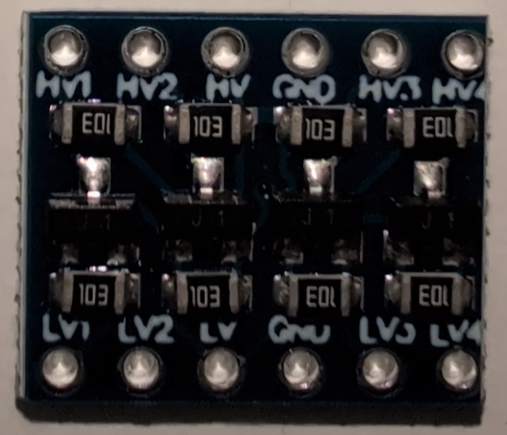
Connections from the Raspi:
- Raspi-pin6 to Shifter-GND, that’s ground
- Raspi-pin1 to Shifter-LV, that’s providing the 3.3V
- Raspi-pin7 to Shifter-LV2, that’s the GPIO 4 of the Raspi
- Raspi-pin29 to Shifter-LV1, that’s the GPIO 5 of the Raspi
Software side
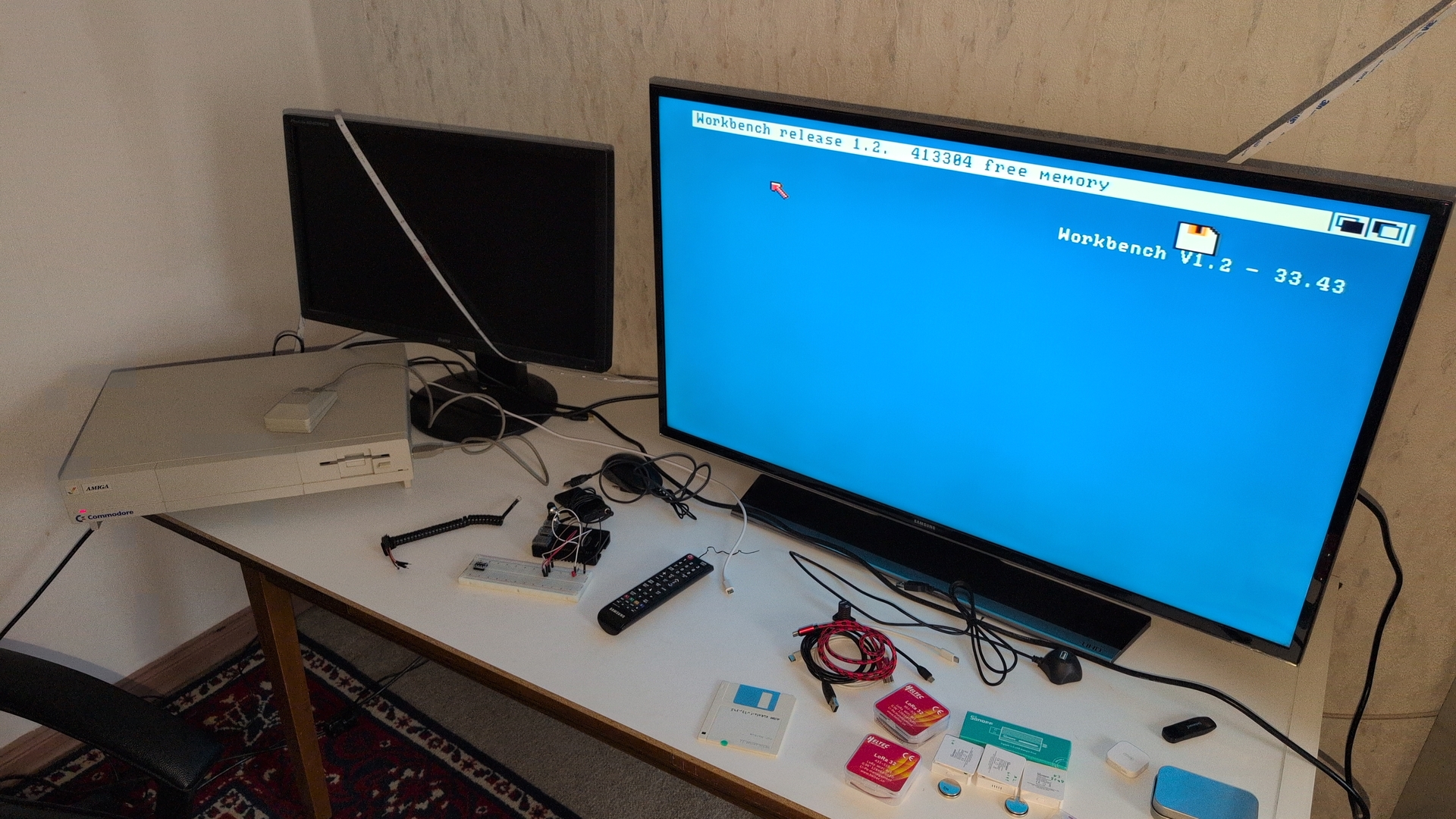
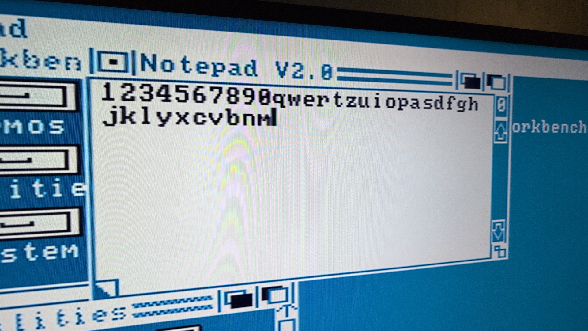
For sending the first key press, I’m booting the Amiga into workbench, and start the notepad - so most key presses should be visible immediately.
For the Raspi side, I used 2 sources:
- Here is an outline of the protocol we need to implement, and a matrix with all the keycodes the keyboard can send
- kbdbabel.org has this fantastic diagram which made things much more clear for me. An excerpt:
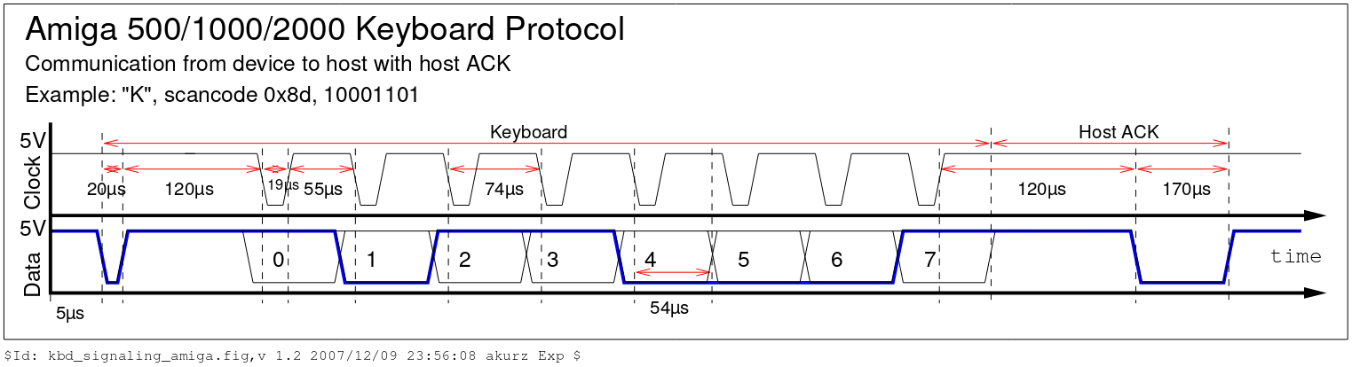
In words:
- both CLOCK and DATA lines are “up” by default
- a single transmission starts with the keyboard taking down DATA for 20μs. Then we wait 120μs.
- then the 8 single bits are transmitted. For each of these, DATA is either taken down (representing a 0) or stays up (representing a 1), and then the CLOCK line is taken down for 19μs. We basically bring DATA into the desired state and then trigger CLOCK to tell the Amiga “now look at the DATA line”.
- the last bit represents the key state, a 0 means “button down” and 1 means “button up”. If we just send “down”, then the Amiga will interpret it in repeated key presses.
- last, there is a final part: my implemntation is here just waiting, but we should seek here for an ACK message from the Amiga.
This graphic is implemented in simple-keypress.py, it’s simply sending the sequence to signal of pressing down the ‘k’ key. If you wired up as per above, this should work now.

Current code base, next steps
The current code, amikey.py, does this:
- enters a loop
- waits for a keypress
- it will lookup that key in a keytable, send the keycode together with ‘key pressed’
- then send the key code with ‘key released’
- enter the loop again
The code is for now at https://fluxcoil.net/files/scripts/202512-amikey.
Details on the files there:
- amikey.py, most usable implementation to send keycodes directly to the Amiga. Once started, you will need to end this code in sending a kill signal from another terminal.
- amikey-input.py, simpler input loop, you need to press return after entering the key code
- amikey-wait-for-ack.py code implementing the attempt to read the ACK from the Amiga
- simple-blink-test.py, simple blinking LED
- simple-input-test-pulldown.py, simple code to test pull down input
- simple-input-test-pullup.py, simple code to test pull up input lines
- simple-keypress.py, the most basic code to send a single keycode
Next steps/future extensions:
- input without a final ‘return’ should be taken in and transmitted
- the code should fetch the ‘host ack’. The code in amikey-wait-for-ack.py is sending k-down and k-up, and after the second keycode goes into a loop for detecting state change from the other side indicating the ACK, but the code is not detecting that. Maybe I should verify if I see an ACK with an oscilloscope, maybe after sending chars in a loop. I could also open the Amiga 500 and try to sniff the protocol there.
- Right now, simple ‘sleep’ are implemented. That’s not accounting for the processing time of the other functions, ideally we would look at a wall clock and act based on that?
Porting to other languages might make this also more portable to other devices. One really fun implementation I’m pondering about: Commodore 64 have a big keyboard, connecting one of these to the Raspi and using the C64 as keyboard for the Amiga would be great!
Corrections? Questions? -> Fediverse thread